Media Feed Setup - Printzone, Media Guides, Sheet Separators, Stacking
Printer is equipped with four Sheet Separators, two Side Guides, and a Rear Media Support Guide with two different sized Wedge Extensions. When properly adjusted these items will separate and guide the media so that only one piece of media is fed into the Print Engine at a time.
Print Zone Reference Tool
A Print Zone Reference Tool is attached to the Feed Table on the printer; near the sheet separation area. It is provided as an aid for positioning the Media Side Guides so the Media passes under the desired area of the printhead (print zone) and as a reference for identifying if the media will pass over the Exit Sensor or not.
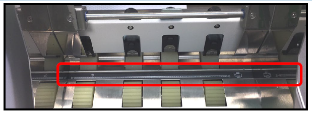
NOTE: The Print Zone Reference Tool identifies the approximate locations of the items identified on the Tool (decal). Some variation can be expected due to assembly tolerances.
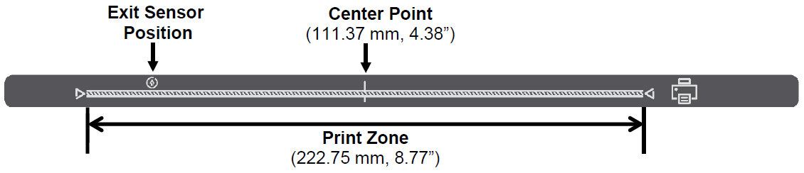
Print Zone: Shows approximate position of print area (222.75 mm, 8.77”) within print engine.
Exit Sensor Position: Shows approximate position of Exit Sensor. If your Media doesn’t fully cover the Exit Sensor symbol; you must select “Ignore Exit Sensor” in the Touchscreen (Job Menu, Media Thickness).
NOTE: Exit Sensor is located under the Exit Transport Cover, on the table top, between Media Transport Belts.
Center Point: Shows approximate center point of the Print Zone (Printhead). This Center Point identifier is useful when primarily using media that measures up to 4.38”. In this case you can position the media so it passes under the left side of the print zone. When the print quality in this area of the Printhead becomes unacceptable (reaches nozzle end of life); you can move media so it passes under the right half of the print zone, set Left Adjustment in the Driver to ~111 mm and select “Ignore Exit Sensor” in the Touchscreen. By doing this you can take advantage of the unused section of the Printhead; thereby extending Printhead life.
Tip: Don’t forget to move the position of the Feeder/Entry Sensor Assembly so it is located over the media’s path.
Position Media Side Guides (Inner and Outer)
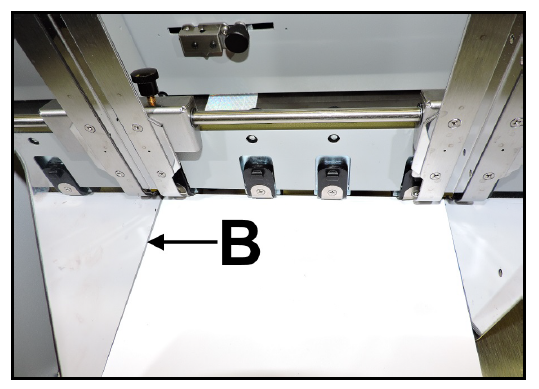
1. Position Media Side Guide – Inner [B] to the desired position and secure it using the locking knob. Then lay a single piece of media into the hopper so it is positioned against Media Side Guide – Inner [B]. Tip: You may need to move the Media Side Guide – Outer [C] to provide room for the media to fit between the Guides. |
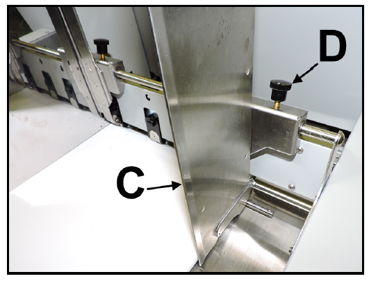
2. Position Media Side Guide – Outer [C] so that it is about 1/32” from the other side of media. Tighten locking knob [D] to secure Side Guide. |
Adjust Sheet Separators
|
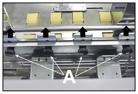
1. Loosen the locking screws, located behind Sheet Separators [A], and raise Separators; then tighten the locking screws to hold the Separators in the “Up” position.
2. Place one piece of Media (thickest area of media) under the Separators. Loosen Separator locking screw and allow Separator to settle onto media. Then tighten locking screw. Repeat for each Separator that has media below it. |
Attach Media Support Wedge Extension
Attach the appropriate Media Support Wedge Extension, if needed, to the Rear Media Support Guide/Sled; as shown below.
|
No Media Support Wedge Extension – For media that is 6” to 17” in length.
Examples:
Letter sized (8.5”x11”) media feeding Short Edge First (SEF)
#9, #10 envelopes feeding SEF
9”x12” envelop feeding SEF
10”x13” envelope feeding SEF
|
|
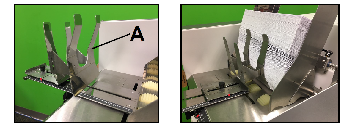
Wide Media Support Wedge Extension [A]
– For media that is 6” to 10.5” in width and 4” to 13” in length.
– For feeding #9, #10 envelopes Long Edge First (LEF)
|
|
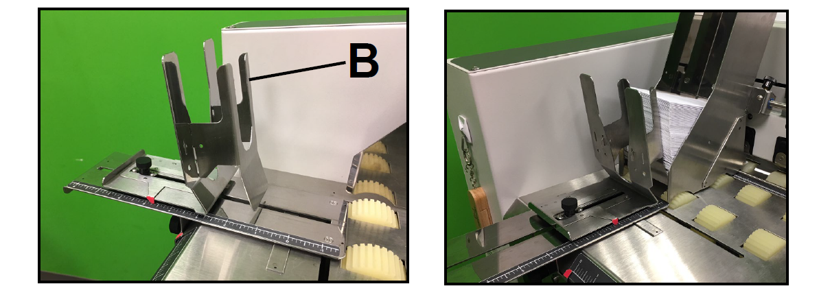
Narrow Media Support Wedge Extension [B]
– For media that is 3.25” to 6” in width and 4.5” to 13.5” in length.
|
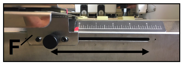
Adjust Rear Media Support Guide/Sled Assembly
|
1. Adjust Rear Media Support Guide [F]. Loosen the locking knob and slide Guide right or left, to center Guide on the width of your media. Then secure locking knob.
|
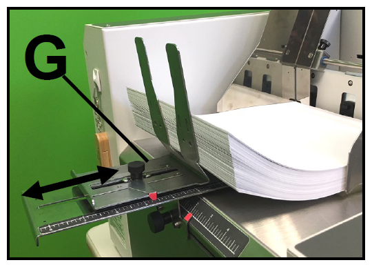
2. Adjust Rear Media Support Sled [G]. Loosen locking knob and move Sled to desired position, to raise/support trailing edge of media. Then secure locking knob. |
|
Examples: Sheet Paper - Raise media ~ 1.25" above Feed Table NOTE: Raising the media too high above the Feed Table will cause loss of contact between media and feed rollers; which can cause hesitation in feed. The Rear Media Support Sled should be positioned so the media stack is being held against the separation area while still providing proper media to feed roller contact. |
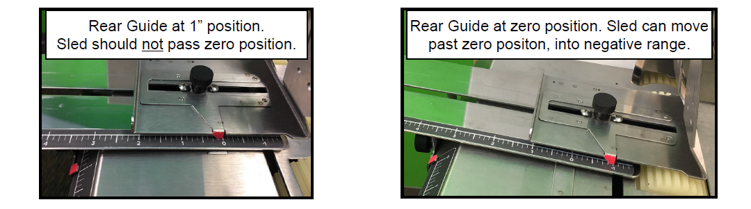
Guide/Sled Positioning Scales & Sled Safety Stop
|
|
A “Safety Stop” is provided to help prevent the Sled from moving past its zero position when the Rear Media Support Guide is not at its zero position. Only when the Rear Guide is at its zero position, should the Sled be moved past its zero position (into negative range).
|
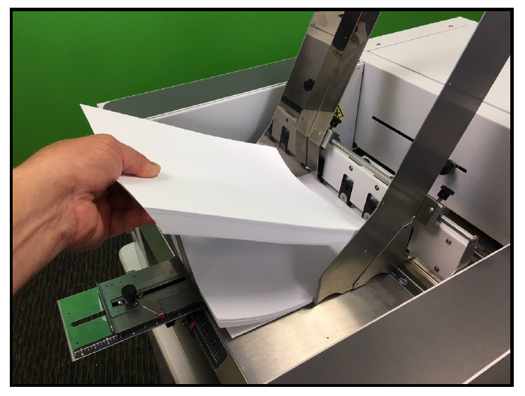
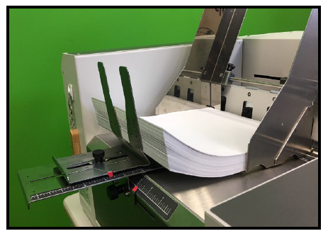
Load Media into Feeder Section (Hopper)
|
Place a stack of media into the hopper. Make sure that the stack is fanned so the bottom piece is closer to the separators then the top pieces.
Tip: When loading an empty hopper. Place one piece of media so it is directly against the tips of the separators. Then place the fanned stack of media on top of this single piece. This will help to reduce the chance of double-feeding (overlapping media) issues when you start feeding. Finding the Sweet Spot The amount of media that can be stacked into the Feeder Section is determined by the weight and size of the material. To keep the printer feeding consistently (without miss-feeds or hesitations), you may need to reduce or increase the amount of media in the stack for a given media size/weight. |